![]()
Thank you for purchasing the PCS-72-FL. In order to maximize
the use of the system, we will review the system operation. The PCS-72FL is a 7
switch 2 relay system with a flasher unit built in. The unit has two relays
controlled by the first two switches, the third switch turns on the flasher
circuit and switch four, five and six are direct connect circuits. switch 7 is a
momentary switch that changes the flash pattern.
We will discuss the system in the following order.
1.
Two relay circuits
2.
Three direct circuits
3.
One flasher circuits and how to make it work in different configurations.
1.
The two relay circuits are used for high current devices. The power for
the device does not go through the switch, the switch is used to activate a high
power relay. The Switch uses smaller wire that only has enough power to engage
the relay.
The two relayed circuits would be used for large light bars.
2.
The three direct circuits the power goes through the switch then to the
device. These circuits are best used for lower power devices like area lights,
interior dome lights, whip lights, reverse lights, rock lights, stereo activate
and intercom.
3.
The Flasher circuit has both a right and left output, in this way you can
create patterns that can go up and down or right and left or both. If set
correctly you can flash curtain lights or make them stay solid without stopping
other lights.
If you want to flash lights that are on another switch so that
you can make them solid or flash then you would install a jumper wire from one
of the flasher circuits over to the light to be flashed, if you want to have
multiple lights hooked up to each side of the flasher then you would need to
install Diode jumpers so you can protect the flasher circuit from turning on all
the lights.
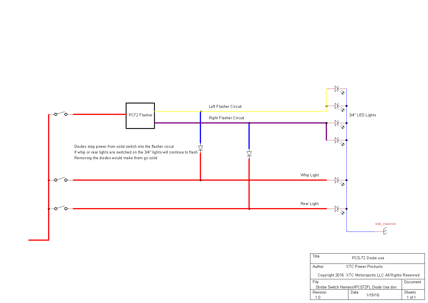
Sample
You want to flash four 3/4" lights - a right and left on the
front and a right and left on the rear. So the right lights would be hooked up
to the yellow flasher output and the left lights would be hooked up to the
violet flasher circuit. Next you want to flash your whip light and your rear
backup lights, if you were to hook a jumper directly from the flash circuit to
the other two circuits, when turned on the power from the solid switch would
also light up the 3/4" lights. To solve this you would install a Diode Jumper so
that the flasher power can go to the whip, but the whip power cannot go back in
to the flasher circuit. The diode only lets power go one way.
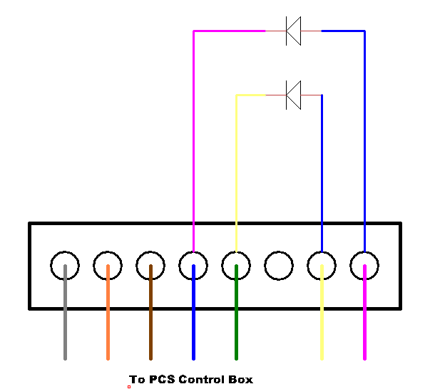
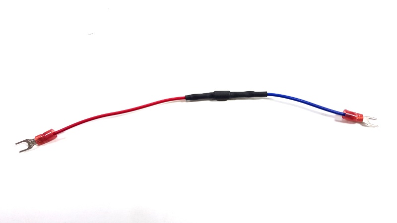
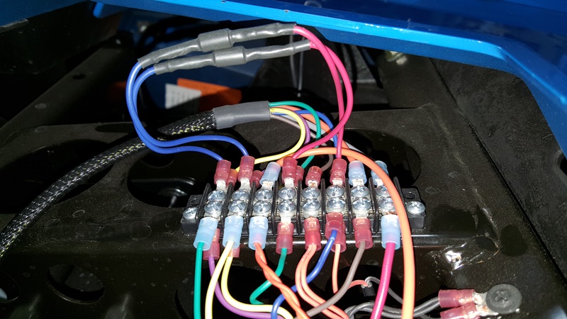
Diode Jumper installation
Jumpers can be purchased on our website at www.xtcpowerproducts.com
For support on installation we can
be emailed at support@xtcpowerproducts.com or
we can be reached by phone at 480-558-8588.
XTC Power
Products
A Division
of XTC
Motorsports LLC
925 N McQueen RD. #101
Gilbert AZ 85233
480-558-8588
Copyright © 2016 XTC MOTORSPORTS LLC All
Rights Reserved