![]()
Honda
Pioneer 1000 Turn Indicator Kit
Thank you for purchasing XTC Motorsports Turn Indicator
Kit. Our Turn Indicator Kit is unique from the other kits on the market. Our Kit
is plug and play , no wires to cut, with only power and ground to hook up, and
plug into the factory harness and use the factory rear brake lights. Since these
vehicles are used primarily for off road use, we use a turn switch on the dash,
instead of those cumbersome turn levers that break off.
Please read the
instructions fully and familiarize yourself with the components before starting
the install.
NOTE: When installing make sure that wires are run away from any hot or moving parts and properly secured.
1. Remove the hood and both tail lights.
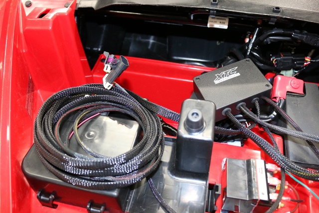
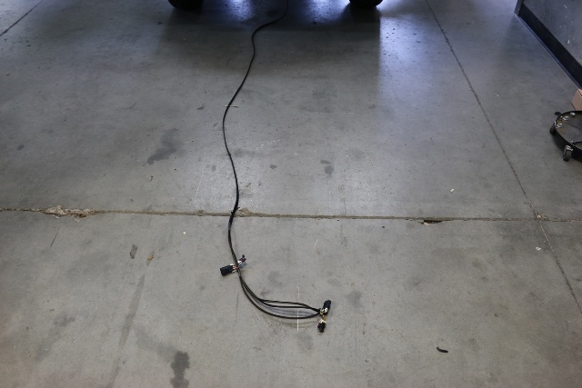
2. Set the kit next to the fuse box and unroll the long rear cable
Note: We found removing the front skid plate can make it easier to run the cable but it can be installed without removing it by removing the seat.
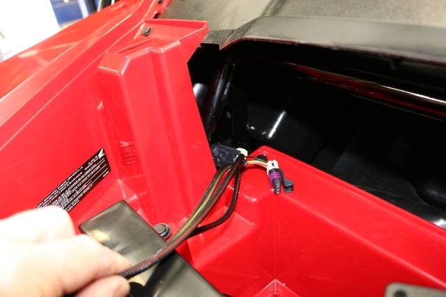
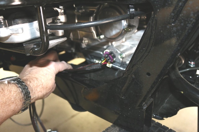
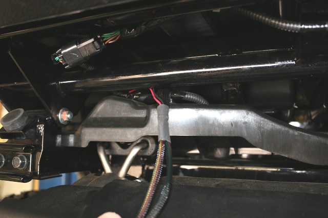
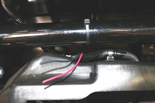
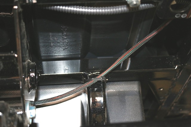
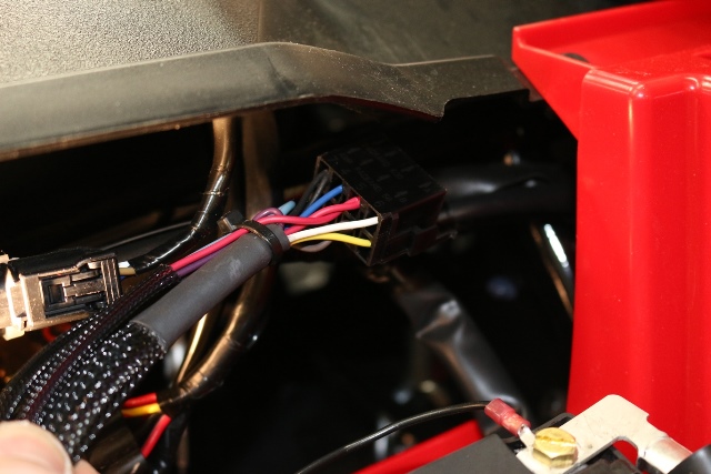
3. Run the long cable down the left side of the opening down along the firewall, along the main power sleeve by the plastic air intake into the center area, go across to the brake line, follow the brake line to the back of the car.
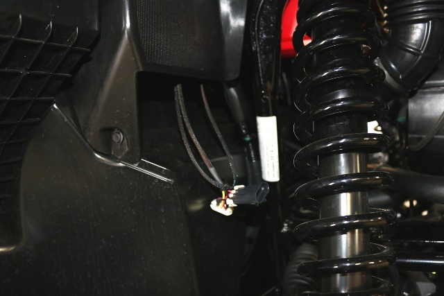
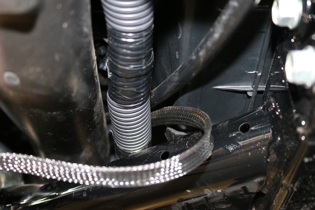
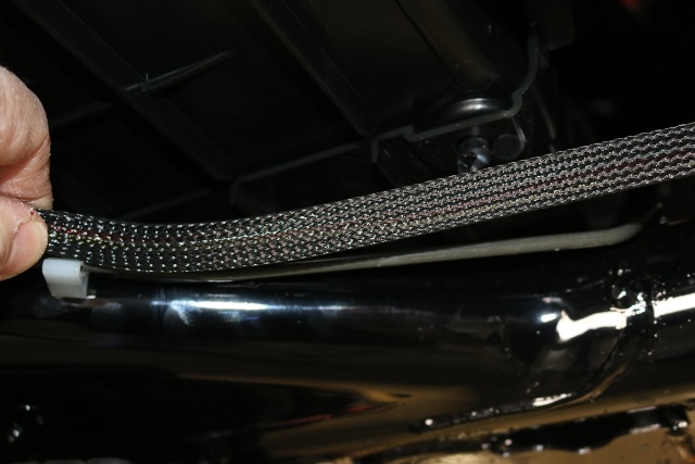
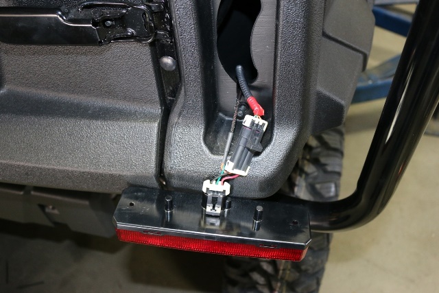
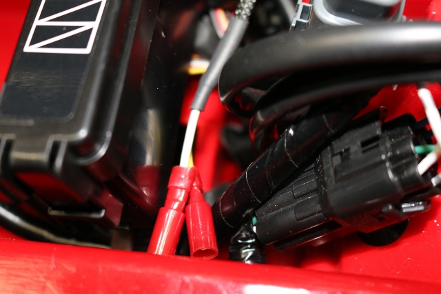
Once you get to the engine in the rear left corner follow the large group of wires up the frame to the rear of the car, out by rear wire harness. The Red and Brown wires are for the License plate light power, secure with cable tie. Run the cables along the inside of the rear near the bed.
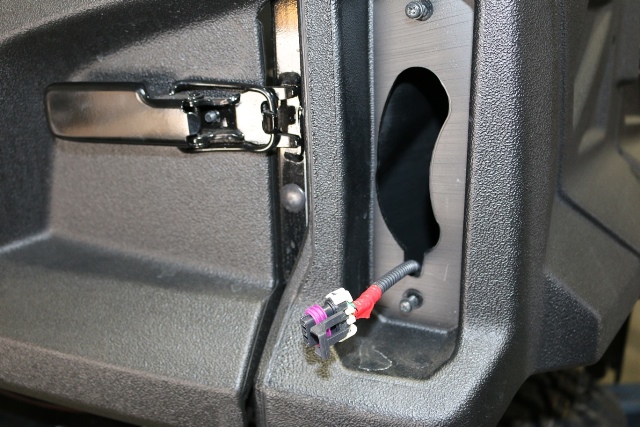
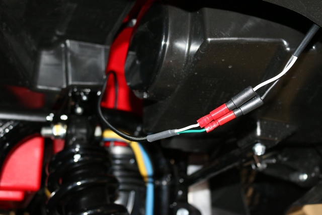
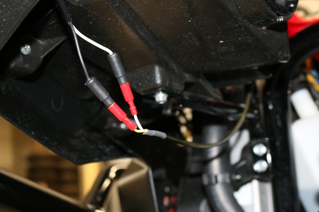
Run the longer wire with the green wire over to the right rear light and up into the rear light housing and secure with provided cable ties to the frame trunk supports. Run the short yellow set over to the left side and secure to supports.
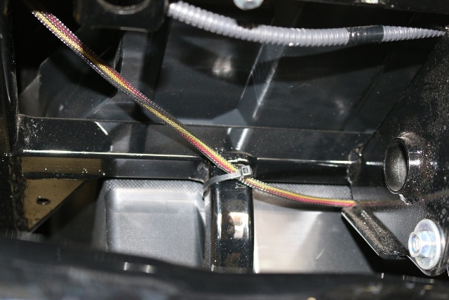
Plug both tail lights in and reinstall. Working your way back to the front, secure the harness to the frame and brake line using the cable tie's provided.
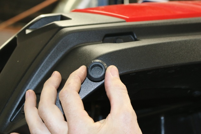
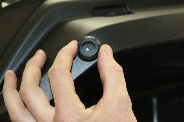
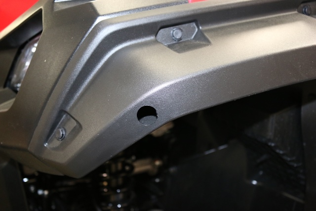
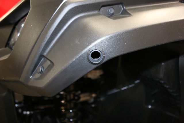
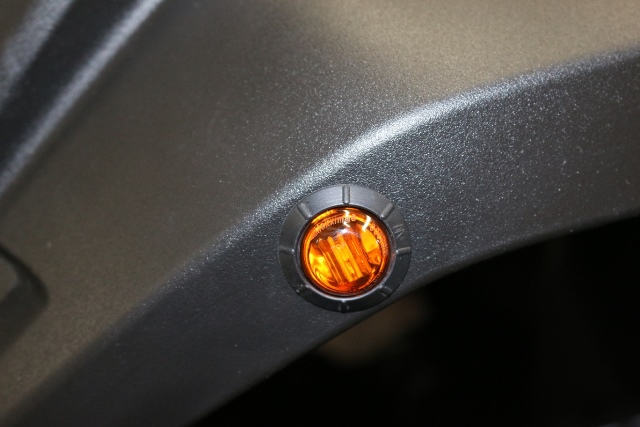
4. Mark and Drill ¾” holes in the front fender and mount left and right turn lights CAUTION: Verify there is proper clearance inside before drilling.
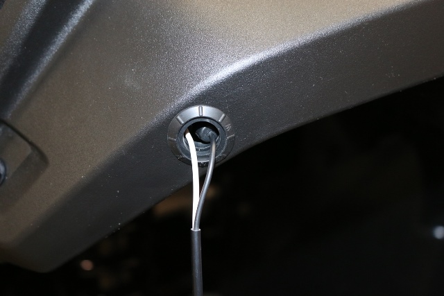
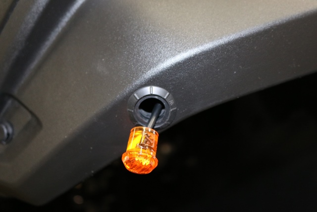
5. Run the cable with the Green and white wire to the right side and plug in, run the yellow and white to the left side and plug in, bring excess wire back toward the control box, secure wires with cable ties
6. Mount Control Box - Using the provided screws mount the control box in open cavity.
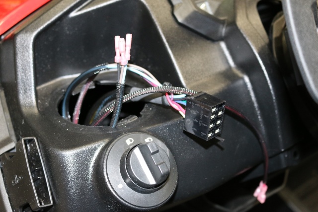
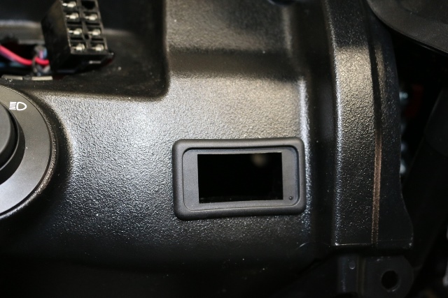
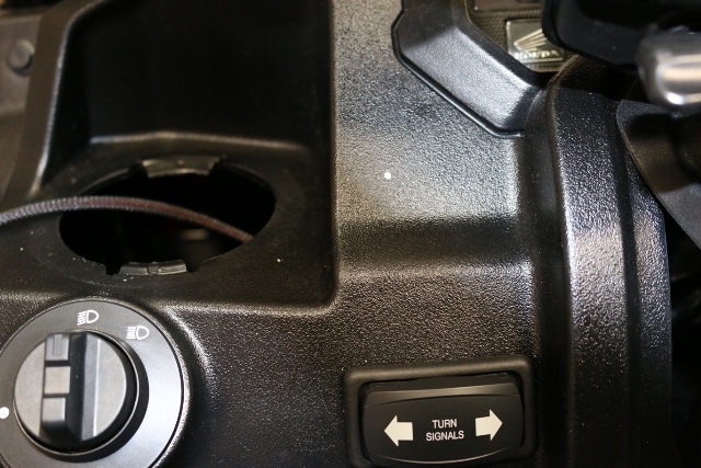
7. Remove the cover under the steering wheel by removing the two fasteners, this will give you access under the dash to run wires, also remove the cup holder on the driver's side.
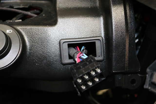
8. Remove the switches from the harness and run to the left side of the steering wheel, keep the wire away from the steering shaft.
CAUTION: Verify there is proper clearance behind dash for the switch before cutting!
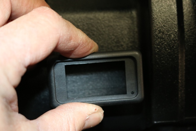
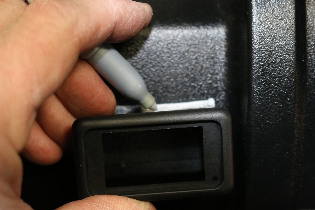
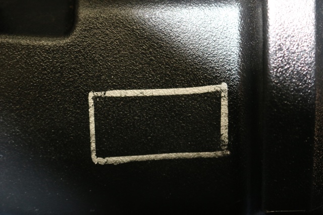
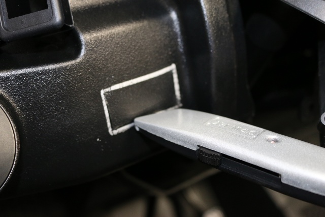
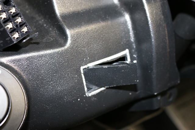
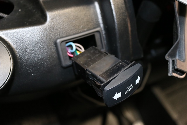
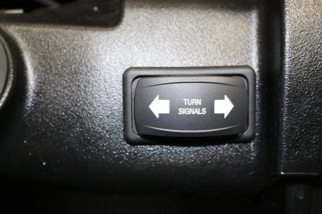
9. Install the turn, horn and hazard switches in dash, using the switch mount as a template mark the rectangle and cut out with a new box knife. Install the switch mount and run the switch connector through the housing and attach the turn switch and install into housing.
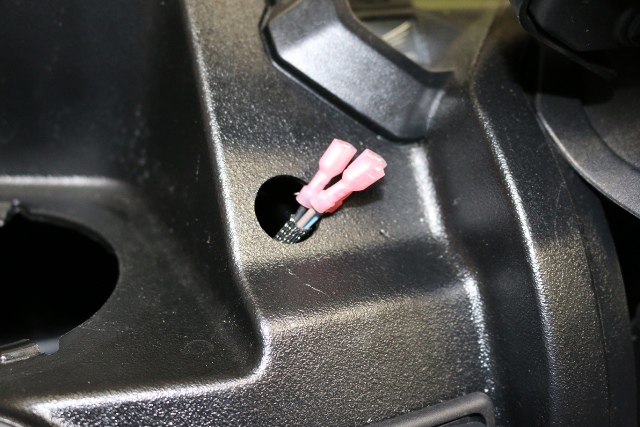
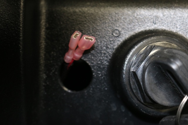
Drill a ¾” hole for the hazard and run the three wires through and re attach to the switch, Black on top, Blue in middle and Brown on bottom.
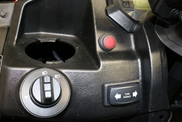
Drill a 13/16" hole for the horn switch, re attach the Red and Violet wires and install in hole.
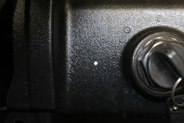
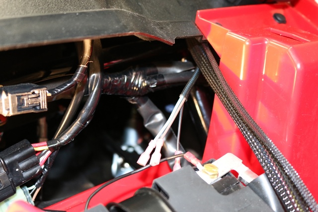
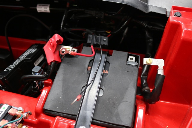
10. Run the power and ground wire to the Battery and attach.
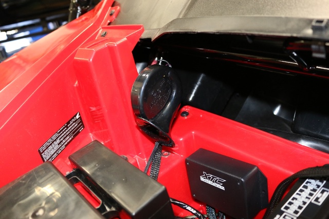
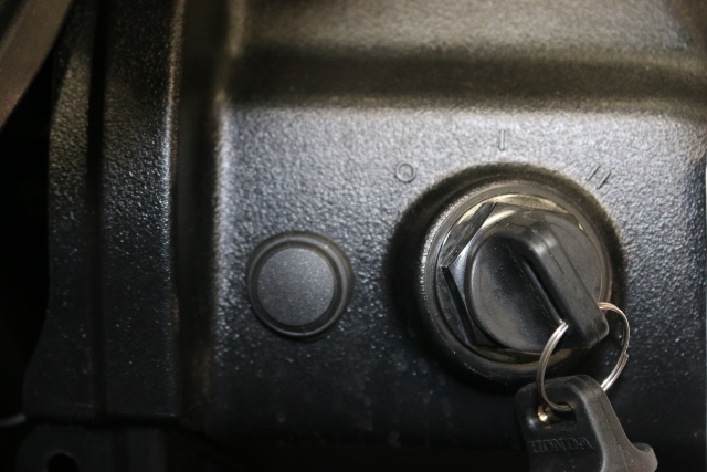
11. Drill a 3/8" hole in the side of the opening and mount the horn using the nut provided. Hook the black and violet wire to the horn.
12. Verify operation of all lights and secure all installed cables with supplied cable ties, re install any OEM parts removed.
support@xtcpowerproducts.com
.
XTC Motorsports LLC
925 N. McQueen Rd.
Suite 101
Gilbert, AZ 85233
480-558-8588
© Copyright 2016 XTC MOTORSPORTS LLC ©