![]()
PCS-64 Power Control System
With RZR 8 Switch Panel
Installation Guide
Thank you for purchasing XTC's Power Control System. The kit comes complete with everything needed for installation. All switch circuit/housings are wired for bottom row lighting for use with optional up-graded Carling lit switches. The system has six circuits, two 10 amp direct and four 20 amp relayed circuits with Diode protection that reduce voltage spikes from field collapse, protecting LED lights and other sensitive accessories. The kit includes power wire with a 50 Amp Circuit breaker for overall circuit protection . More installation information can be found at www.xtcmotorsports.net/install
Please read the instructions fully and familiarize yourself with the components before starting the install.
STEP 1 Remove the front hood, dash cover, seats and center plastic tunnel.
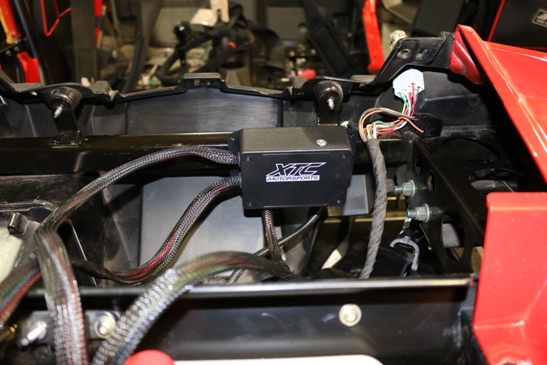
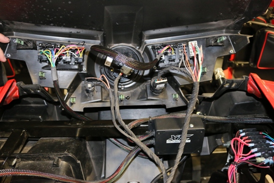
STEP 2 Mount the power control unit on the cross bar under the dash with included self tapping screws
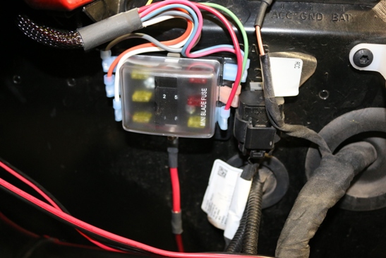
STEP 3 Mount Fuse box on fire wall near factory barrier strip. See photo above.
Step 4 Mount the barrier strip. Access to the barrier strip is only needed occasionally, we suggest mounting the barrier strip under the dash.
NOTE: For XTC's
Switch Mounting plate follow these steps, if not using our switch mounting
plates go to step 8.
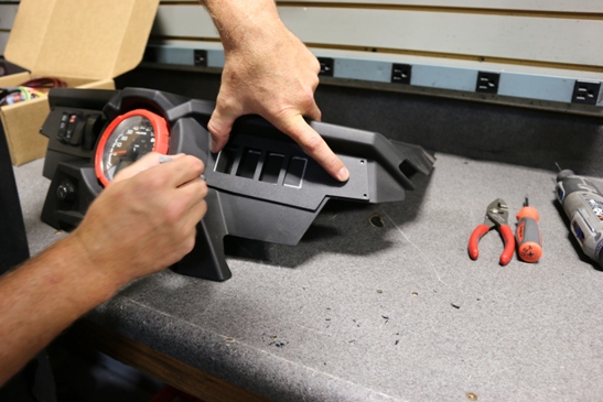
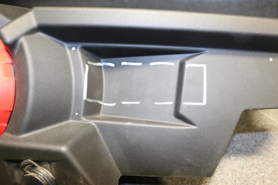
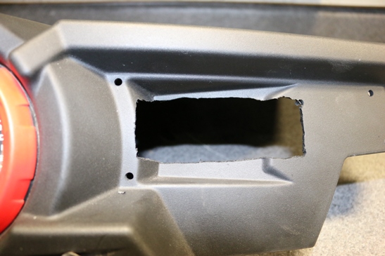
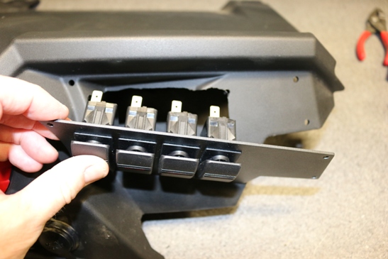
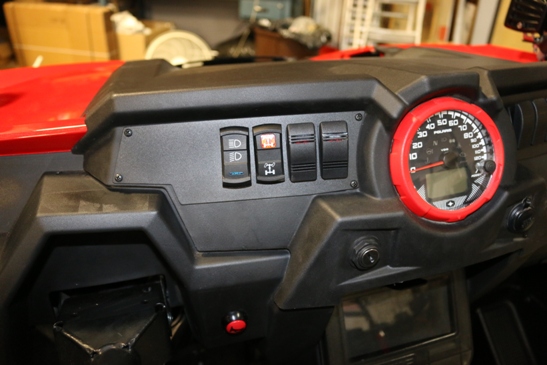
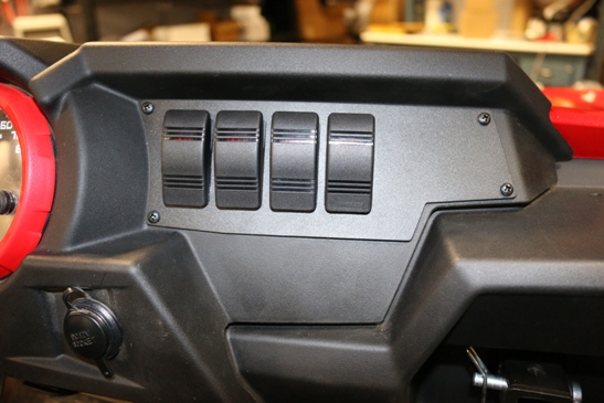
Step 5 Remove Factory switches from the Dash Cover. Using the Switch Plates as a template, mark both sides and each set of mounting holes . Drill the mounting holes and some starter holes. Using a cutout tool cutout the rectangle where the switches will mount. Remove the switches from the harness and install the switches into the mounting plate's along with the 2 factory switches, verify fit on both sides and trim as needed.
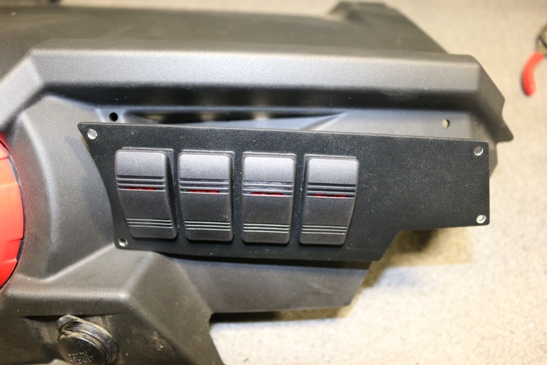
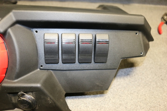
STEP 6 Remove switch plates from dash mount and slide back into dash and mark all 4 outside holes on the fixed dash and drill for mounting screw clearance.
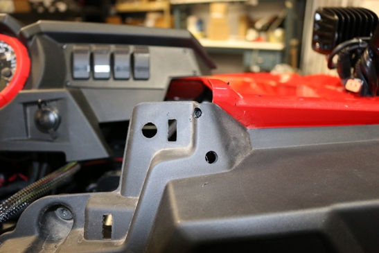
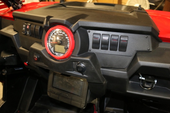
STEP 7 Re-install the switch plates into the dash cover and using the 8 supplied screws and nuts secure the switch plates.
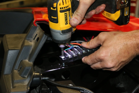
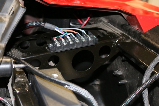
Step 8 Connect the power wire from the devices to be controlled to the appropriate terminal on the barrier strip making sure to attach the devices ground.
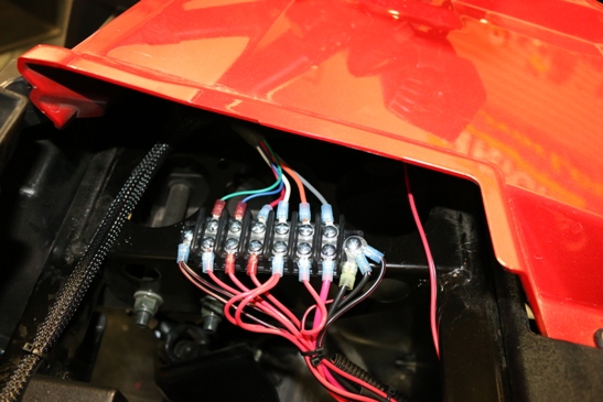
Switch 1 through 4 should be used for your larger accessories and are on power relays, switch 5 and 6 the power goes through the switch and are used for smaller items like whip light, interior lighting or stereo. The following are the switch designations.
1. Terminal 1 is Grey and is on relay 1 controlled by switch 1 with 20 amp fuse
2. Terminal 2 is Orange and is on relay 2 controlled by switch 2 with 20 amp fuse
3. Terminal 3 is White and is on relay 3 controlled by switch 3 with 20 amp fuse
4. Terminal 4 is Red and is on relay 4 controlled by switch 4 with 20 amp fuse
5. Terminal 5 is Blue and is direct and controlled by switch 5 with 10 amp fuse
6.
Terminal 6 is Green and is direct and
controlled by switch 6 with 10 amp fuse
STEP 9
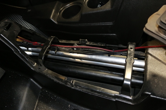
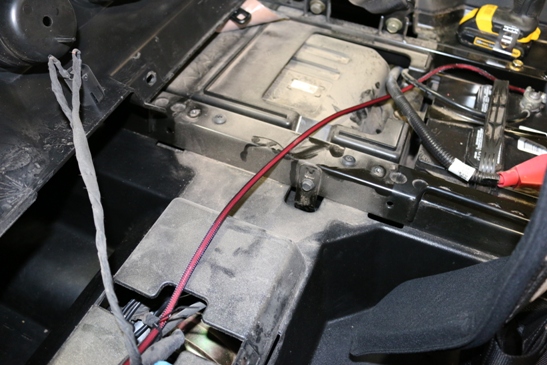
Run the power cable to the battery. The power cable is run through the center
plastic housing to the battery under the seat. Remove seats from the car and
remove the plastic tunnel that runs down the center of the car.
Run the power cable
from the fuse block down to the center cavity then along the seat belt
attachment points to the battery.
Using the supplied cable ties, secure the cable making sure to keep the cable
away from any Hot or Moving parts.
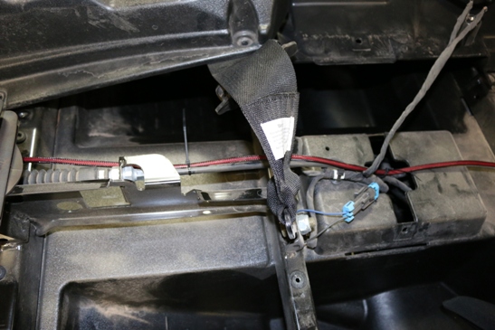
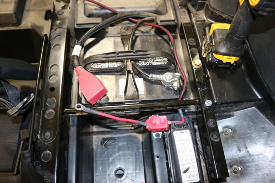
Attach the wire to the 50 amp Circuit breaker provided. Run the short wire from the circuit breaker to the positive post on the battery. If installing in 2 seat car the cable maybe shortened or coiled up. Secure power cable with the included cable ties.
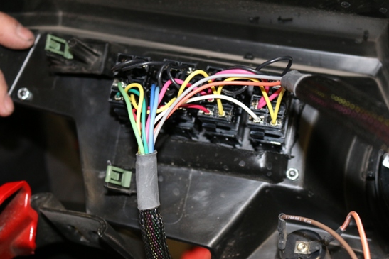
STEP 10 Install the dash cover back into the care. The two switch connectors go to the left hand side next to the factory switches. the others are connected in a row for switch 3, 4, 5 and 6.
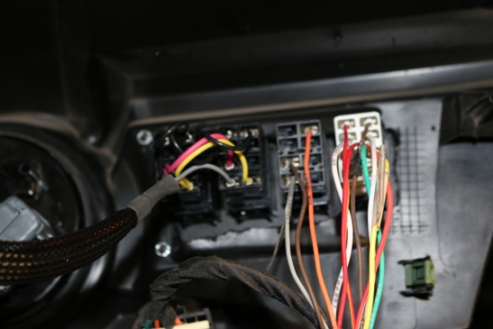
Step 11 The yellow wire is power to the bottom row lights when upgraded switches are installed *See Below. If used attach the yellow wire to the keyed positive power post on the OEM barrier strip on the fire wall, this will turn on the bottom switch lights when the key is turned on.
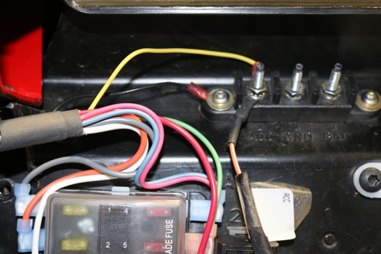
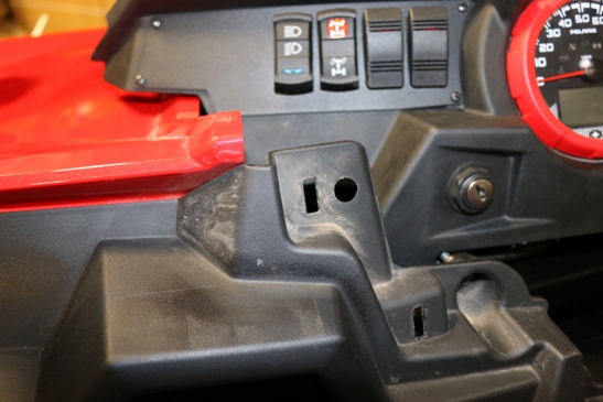
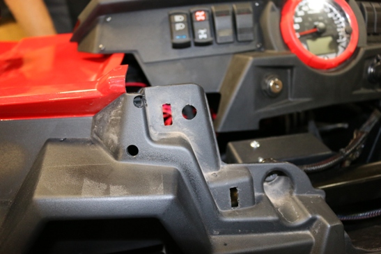
Step 12 Attach the black wire from the harness to chassis ground. (Note: 2015 Polaris RZR OEM front barrier strip post is not attached to ground as labeled). The barrier strip is attached to the chassis with two bolts and they may be used for ground attachment point as shown.
Step 13 Verify operation and re install center console, seats, dash and hood.
* Optional: The harness is prewired for bottom row lit switches. We supplied basic switches since they can be lit and labeled in so many ways. When upgrading the switch use Carling SPST Switch with independent Bottom Row Lighting .
|
CARL - V1D1JCBB-00000-000 |
SPST SWITCH CONTURA V RED/BLUE IND LED |
|
CARL -V1D1JCCB-00000-000 |
SPST SWITCH CONTURA V RED/RED IND LED |
|
CARL - V1D1JBBB-00000-000 |
SPST SWITCH CONTURA V
BLU/BLU IND LED |
Cables and switches above can be purchased at www.xtcpowerproducts.com
More information on installation may be seen at www.xtcmotorsports.net/pp/install. For support on installation we can be emailed at support@xtcmotorsports.net or we can be reached by phone at 480-558-8588.
XTC Power Products
A Division of XTC Motorsports LLC
925 N McQueen RD. #101
Gilbert AZ 85233
480-558-8588
Copyright © 2015 XTC MOTORSPORTS LLC All Rights Reserved