![]()
2016 Polaris General Turn Indicator Kit
Thank you for purchasing XTC Power Products Turn Indicator Kit. Our new Easy
Install Turn Indicator Kit is unique from the other kits on the market. This kit
is completely plug and play , no wires to cut, no crimping with only power,
ground and plug it into the OEM harness. Like many cars on the road today, our
kit uses the factory brake lights as turn indicators. The new General does not
require pulling the car apart to install the turn kit, only the Hood, one
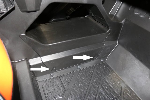
inspection panel and the dash storage box need to be removed, that's it!
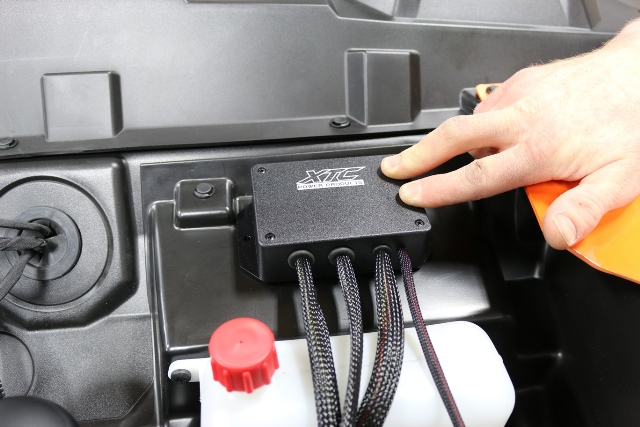
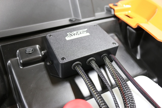
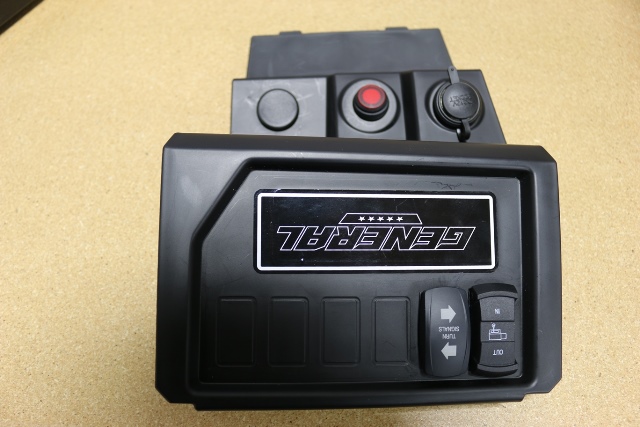
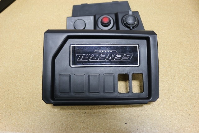
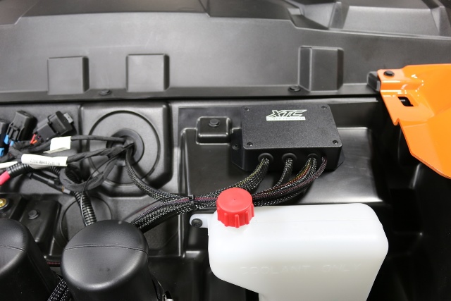
2. Mount the Control Unit as shown using two self tapping screws provided.
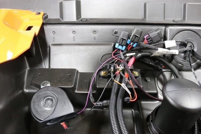
3. Mount the fuse holder on the fire wall using the provided self tapping screw

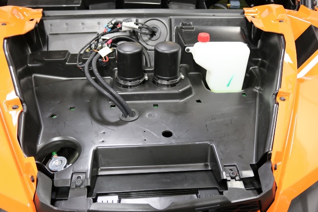
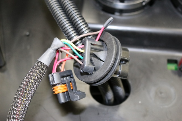
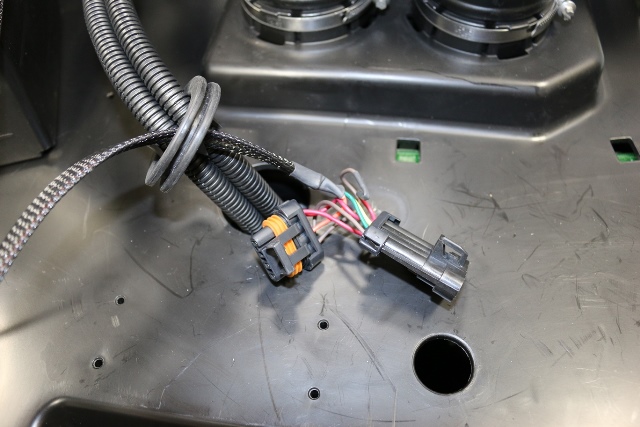
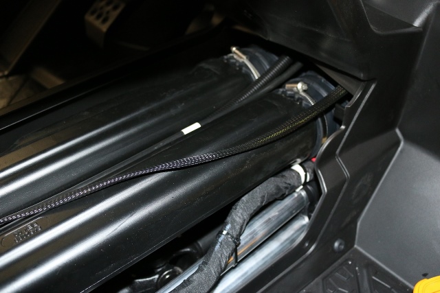
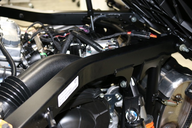
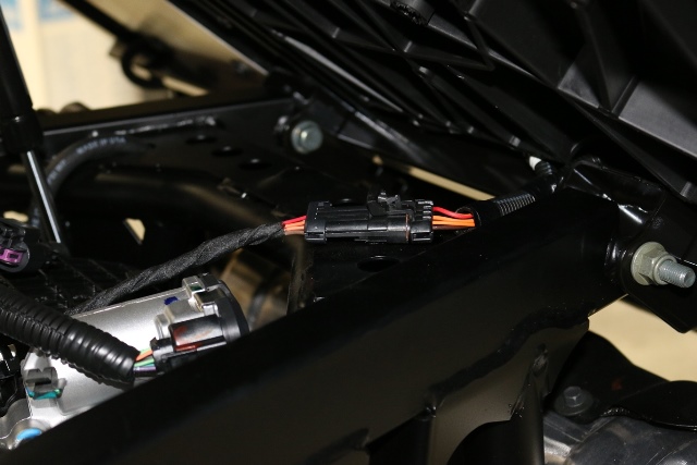
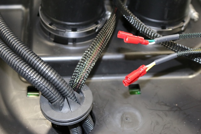
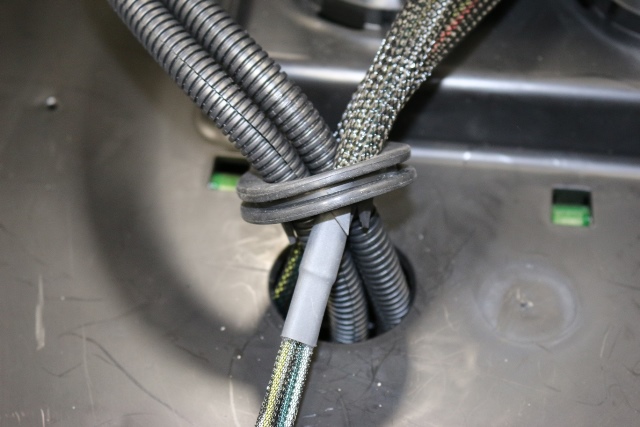
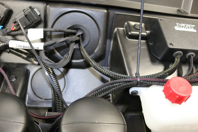
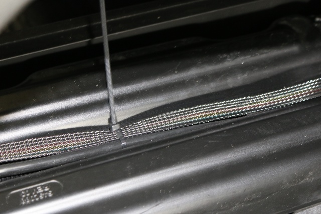
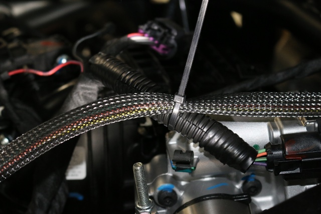
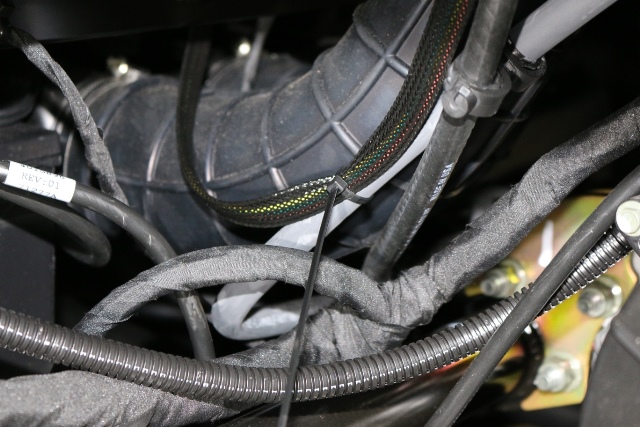
4. Run the long rear harness through the rubber grommet by the air intake tubes to the center of the car. Follow those tubes down through the center console. The grommet may be removed to stretch over connectors then re-installed.
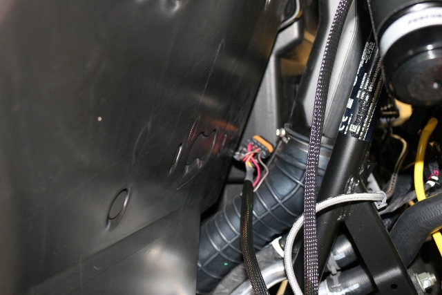

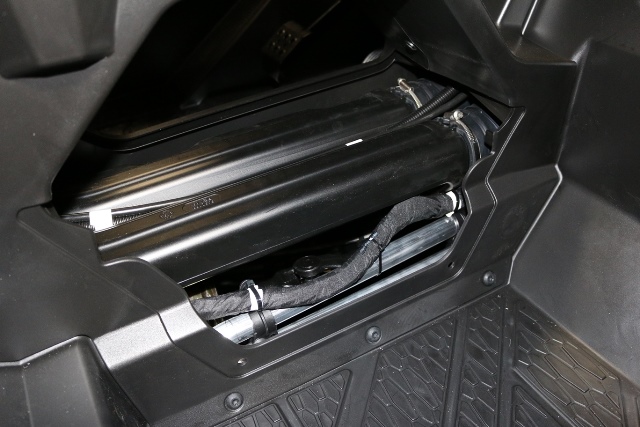
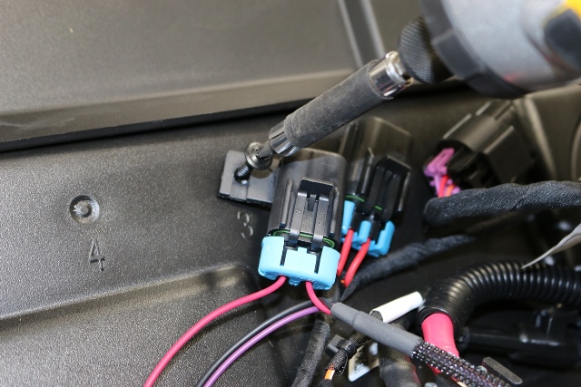
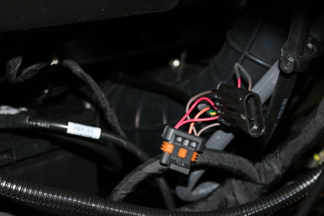
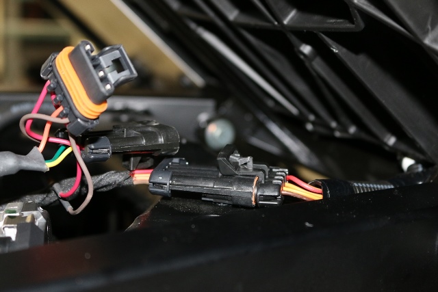
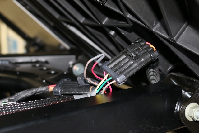
Pull harness through center inspection panel and push toward the rear along tube. Go to the rear and finish pulling it out along the air intake up to the rear OEM connector. Unplug the connector by pulling up on the tab and plug the new harness into those connectors. Make sure to secure the harness with the included cable ties. Note: There is a Red and Brown power wire provided for power to an optional license plate light).
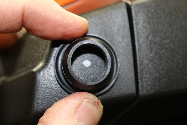
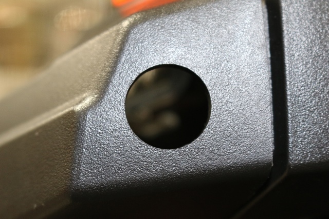
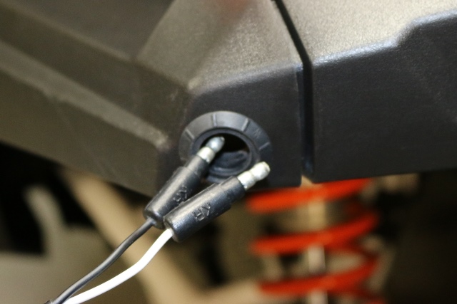
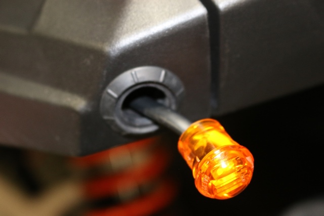
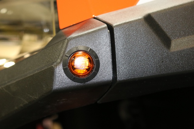
5. WARNING! Verify that there is clearance where you want to mount the front LED lights before drilling the holes. Drill ¾” holes in the front corners to mount the right and left LED's, remove the rubber grommet from the LED and insert into the hole, then re insert the LED into the grommet. The Lights may be mounted anywhere on the front of the car, for the sample we chose the corner of the trim because it can be seen from both the front and side of the car, however the clearance is very tight. If choosing this location use the rubber grommet as a template and mark as far forward and as low as you can to avoid lip on inside.
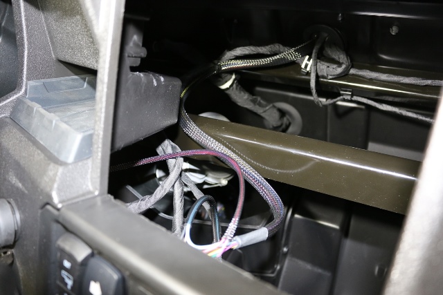
6. Run the front right and left wire harness through the center grommet as shown, the green and white wire go to the right side of the car and the yellow and white go to the left side, connect the green wire to right black wire and yellow wire to left black wire and white to white on both. NOTE: The Black LED wire is positive and goes to the yellow and green wires, they will not work if reversed, white is ground. Secure the Harness using the provided cable ties.

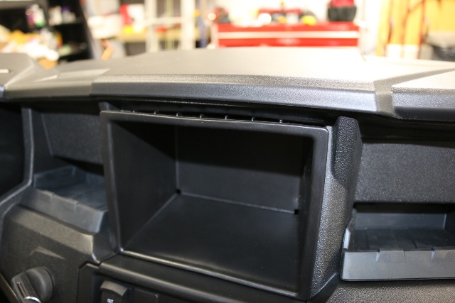
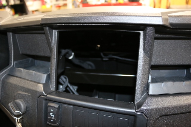
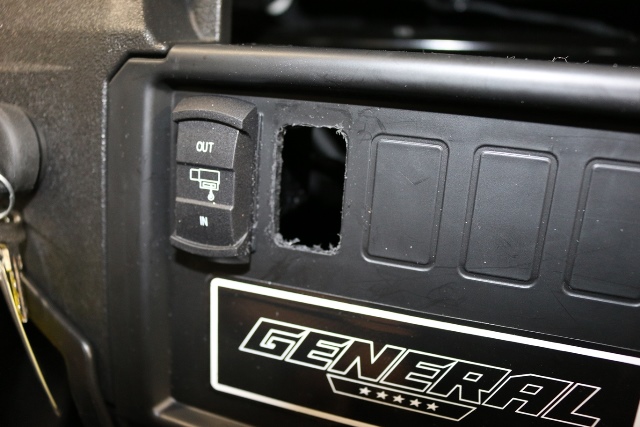
7. Remove the center dash storage box by pulling down on top and out as shown. The switch cutout can be cut in the dash or the switch panel can be removed by pushing out on it. Using a new sharp razor, cut the switch rectangle out. Do not over cut, try inserting switch and trim as necessary. It helps to rock the razor to cut.
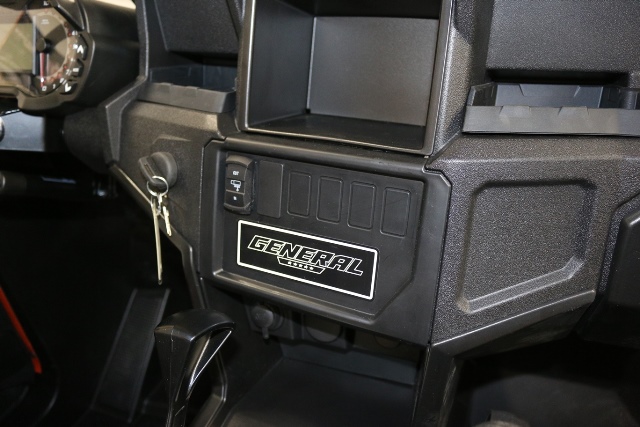
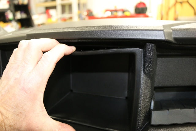
Remove Dash Storage by pulling down on top.
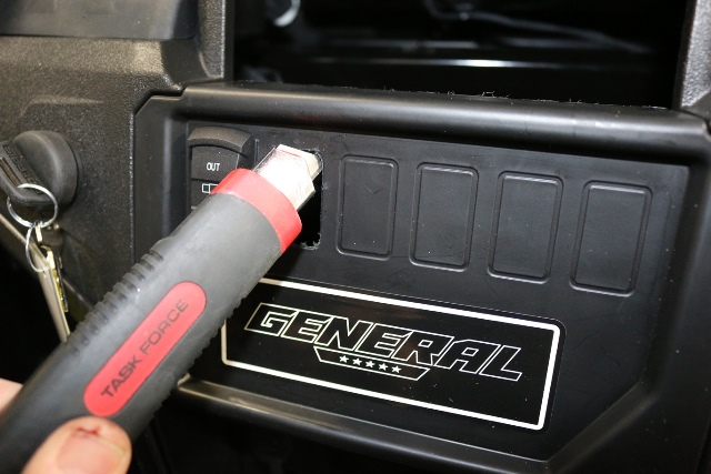
Trim Rectangle out
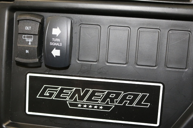
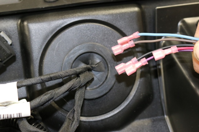
8. Remove the horn and hazard switches from the harness and push the wires through the grommet in center as shown below, then push the 8 pin switch connector through. Note: The grommet can be removed and stretched over the switch connector and reinstalled. Run the 8 pin connector through the rectangle switch cutout and connect to turn switch and slide switch into dash as shown.
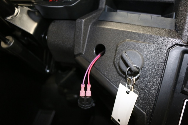
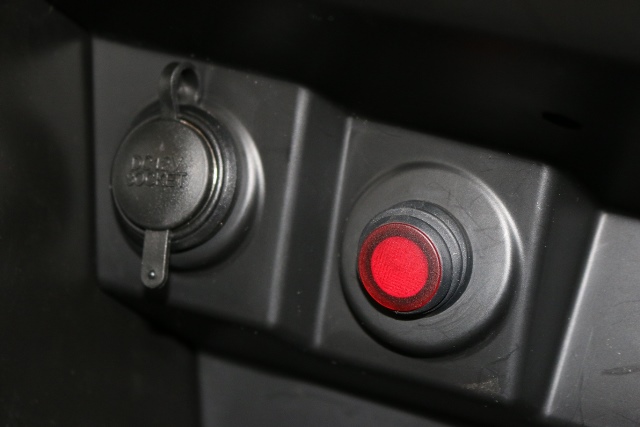
9. WARNING! Verify that there is clearance behind dash for switch's. Mark and drill a 13/16" hole next to the key for the horn switch, run the red and violet wires from the turn switch over to the horn switch and attach and install.
Mark and drill 13/16" hole for horn button

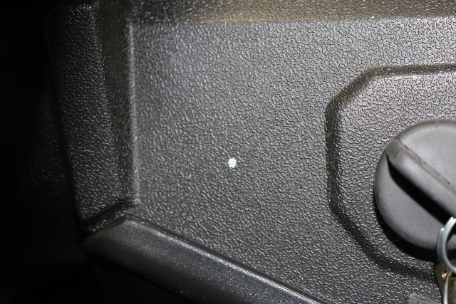
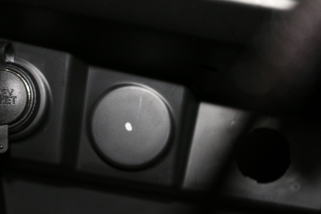
Drill a ¾” hole for the hazard switch under the switch console in the center position. Run the other three wires from the turn switch through the hole and attach to the Hazard switch, Black wire to top bronze, Blue wire middle, and brown wire bottom, push the switch into the hole.
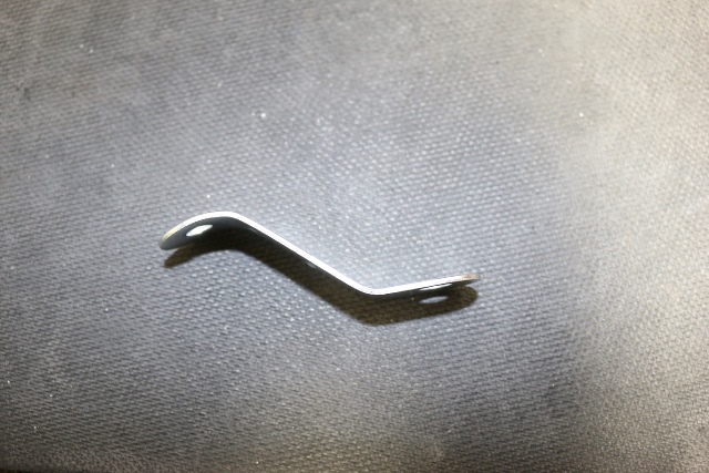
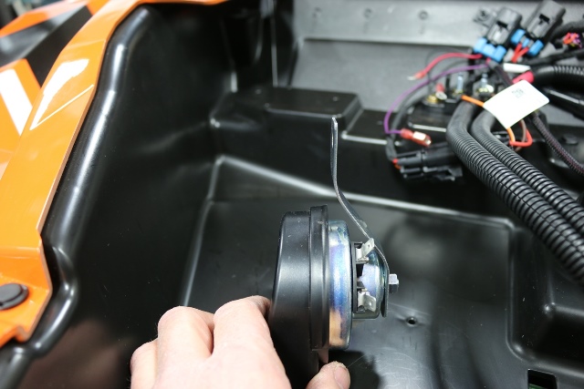
10. Install the Horn. Using two pairs of pliers bend the horn mounting bracket into a Z bend as shown. Mount onto the horn, using the included #10 x 1" screw, mount the horn into the hole closest to the front left area as shown.
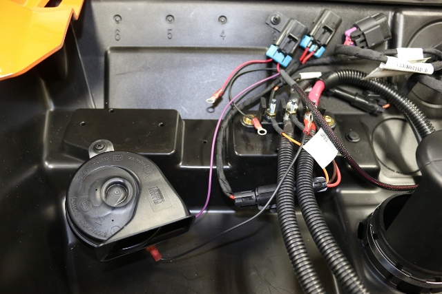
Connect the violet wire to one of the horn terminals and the black wire provided to the other terminal, run the black wire over to Buss Bar and attach to ground. If the car has not been upgraded with the Buss Bar Power Up Kit or Winch Kit then the black wire will need to be grounded to the buss bar mounting screws
11. Run the power wire from the fuse that was mounted earlier to the 12vdc accessory stud on the bus bar, also attach the black wire to ground.
(Note: The car does not
have ground hooked on any of the studs under the hood unless the Bus Bar Power
Up kit or Winch kit are installed, the first stud is keyed 12vdc, second stud is
ground if wired and the third stud in battery direct if installed,
but no fuse or circuit breaker.
You must run a ground wire from the
chassis to the ground stud or run our black ground wire directly to the chassis
for a ground if upgrade is not installed)
12. Verify operation of all lights.
13. Using the provided Cable Tie's secure the harness completely.
14. Reinstall center inspection panel, center dash storage and hood.
We can also be reached by email at support@xtcpowerproducts.com
XTC Power Products
A Division of XTC Motorsports LLC
925 N McQueen RD. #101
Gilbert AZ 85233
480-558-8588
www.xtcpowerproducts.com
*Disclaimer: This kit is intended for off road use only and XTC Motorsports claims no responsibility for it use. It is up to the purchaser to make sure it complies with all Federal, State and Local laws.
Copyright © 2016 XTC MOTORSPORTS LLC, all rights reserved.