![]()
XTC MOTORSPORTS INSTALL INSTRUCTIONS FOR THE HONDA PIONEER 500
Thank you for purchasing XTC Motorsports Turn Indicator Kit. Our Turn Indicator Kit is unique from the other kits on the market. Our Kit is plug and play , no wires to cut, with only power, ground and brake to hook up. The 500 only comes with a single center tail light for the brake, our kit adds a 4" LED bar to each rear fender making it easier to be seen. Since these vehicles are used primarily for off road use, we use a turn switch on the dash, instead of those cumbersome turn levers that break off.
Please read the instructions fully and
familiarize yourself with the components before starting the install.
NOTE: When installing make sure that wires are run and kept away from any hot or moving parts and properly secured.
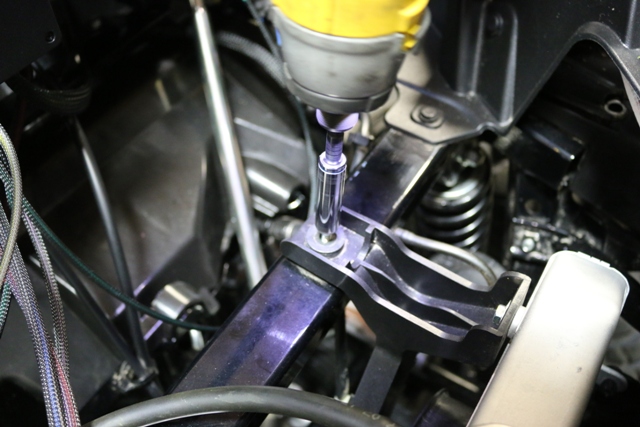
Remove hood and mount the control box in the center on the cross bar using the self tapping screws supplied and attach the ground wire to chassis with supplied screw.
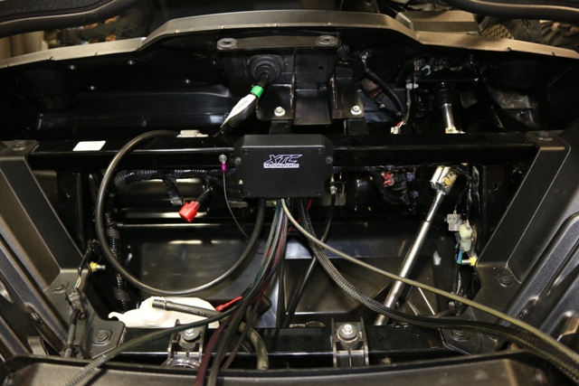
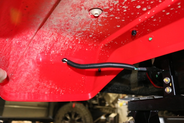
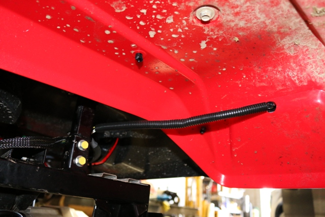
Run the long cable down the driver side wheel well following the brake line into the cavity that goes to the rear, then up the frame to the left rear at the frame corner then over to the right side.
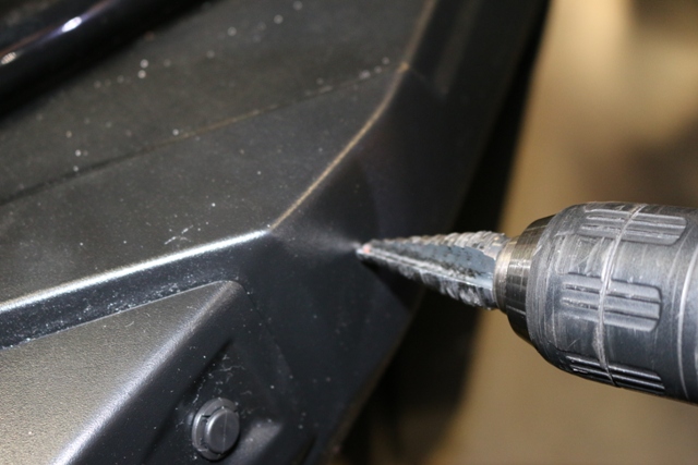
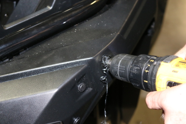
Drill a ¾” hole in the front fenders and mount left and right turn lights
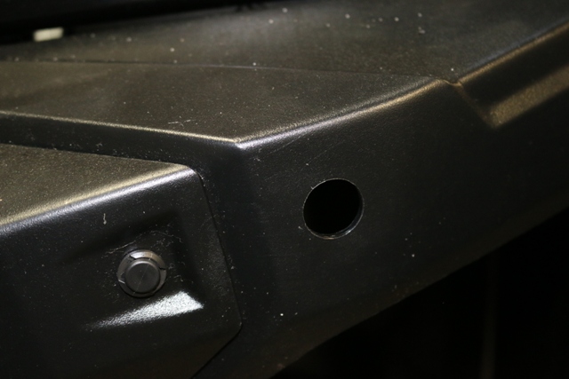
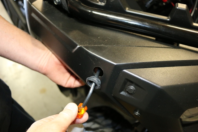
Remove grommet from LED and push wire through then install grommet in hole,
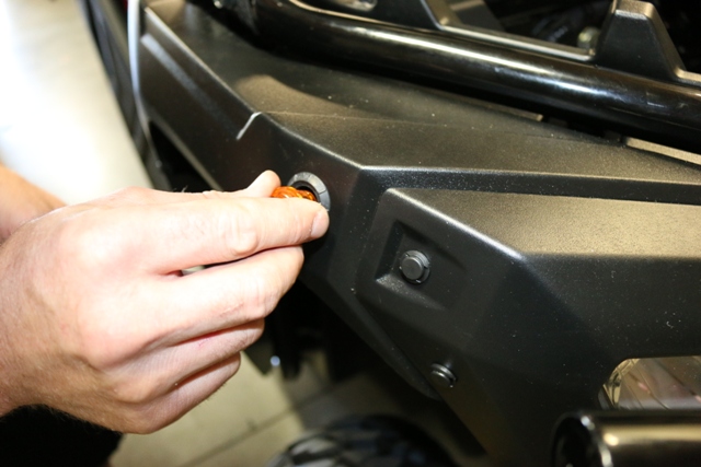
Slide LED into grommet, if it is tight you can use soapy water to help slide it in.
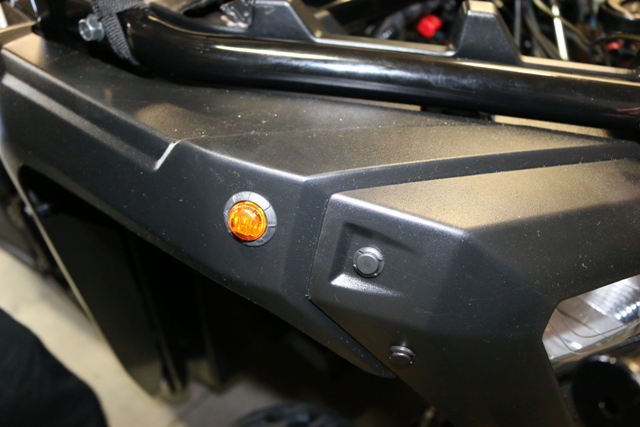
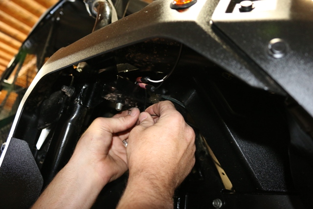
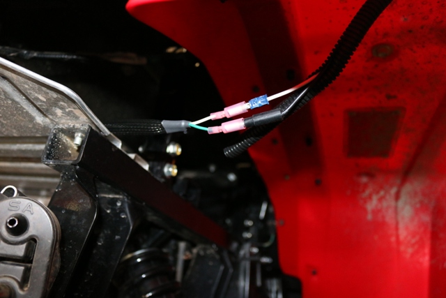
Run the Green and white wire to the right side and plug in, run the yellow and white to the left side and plug. Cable tie Harness
Find an appropriate location to install the Hazard switch, drill out a ¾” hole. Always make sure there is clearance behind where you want to mount the switch
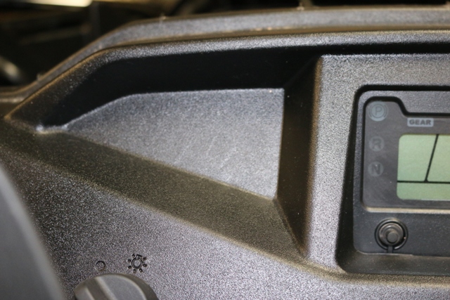
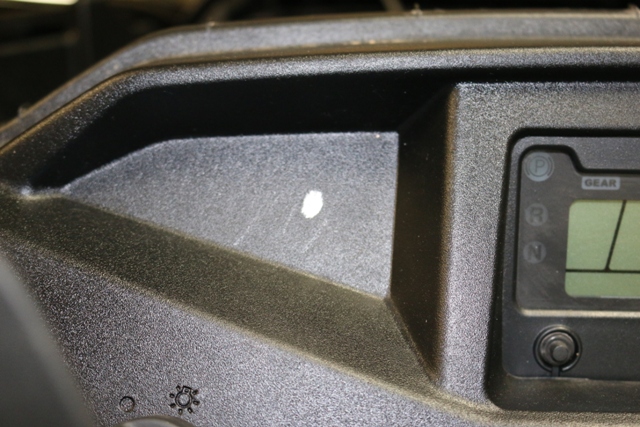
Mark and drill hole.
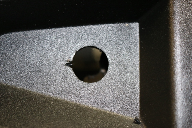
Run wires through hole
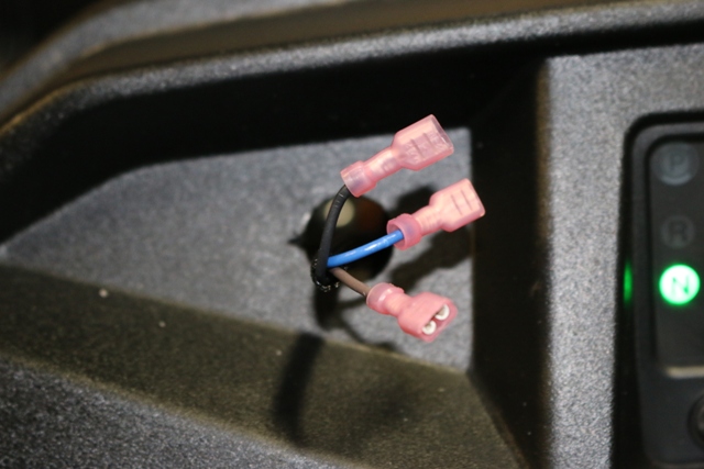
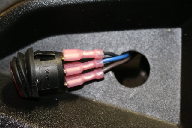
Attach wires to switch, Black to top, Blue in middle and Brown on bottom
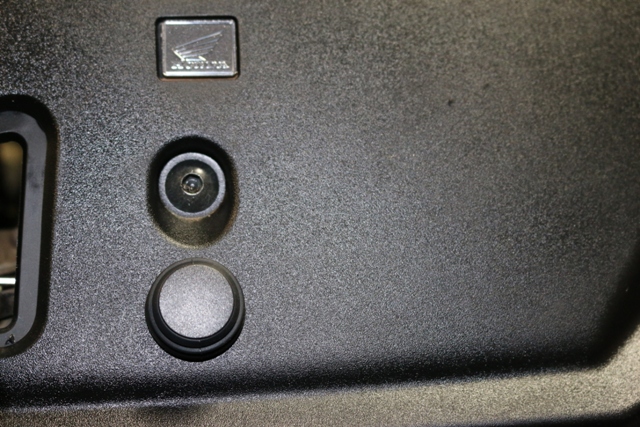
Find an appropriate location to install the Horn Switch. Always make sure there is clearance behind where you want to mount the switch.
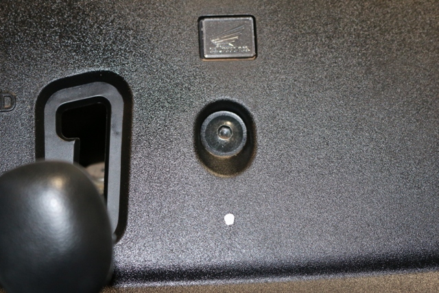
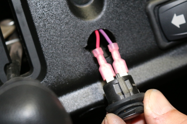
Mark and drill 3/4" hole and notch, push the red and violet wires through hole, attach and install.
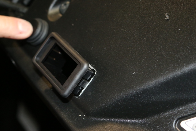
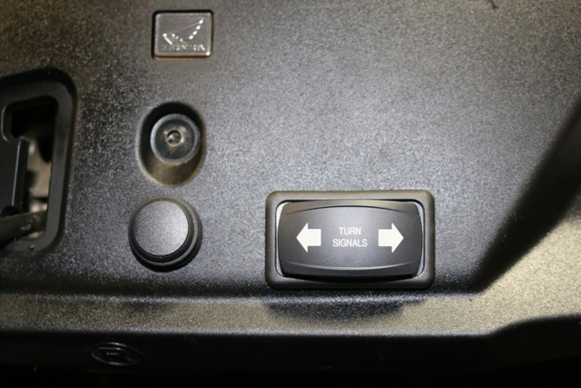
Find an appropriate location to install the Turn Switch. Always make sure there is clearance behind where you want to mount the switch.
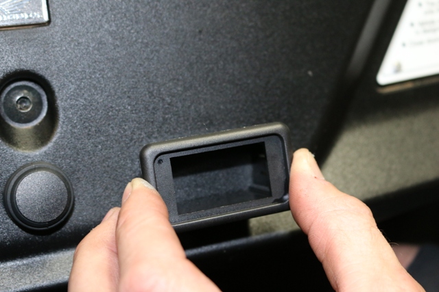
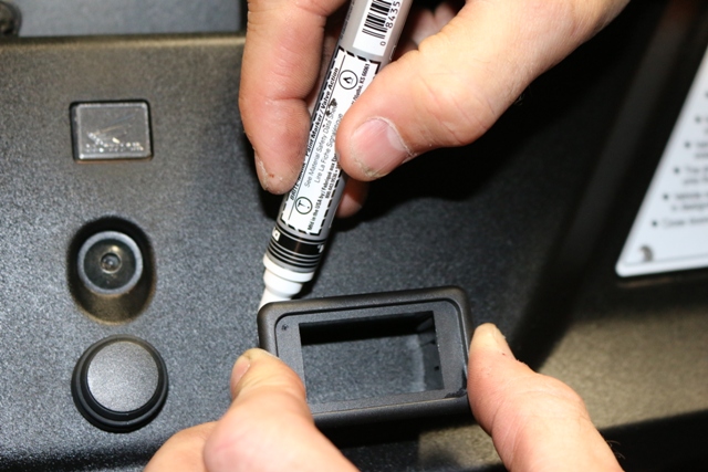
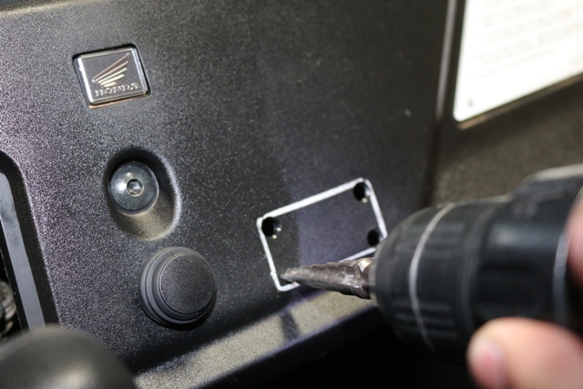
Using the switch mounting plate as a template mark the position. Always make sure there is clearance behind where you want to mount the switch.
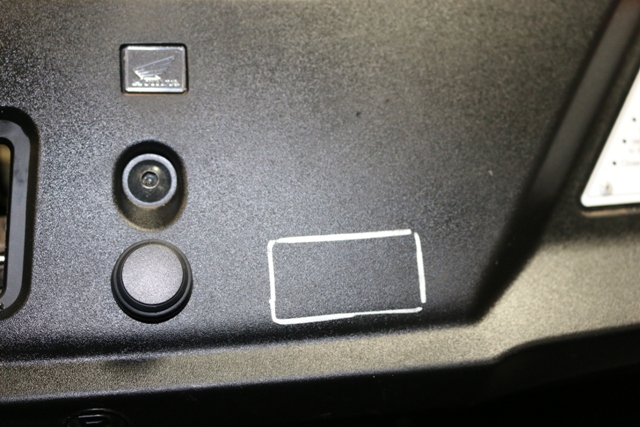
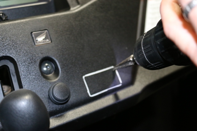
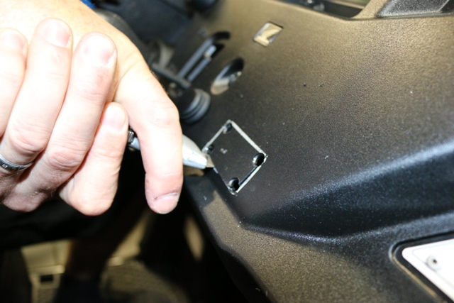
Drill a hole in each corner
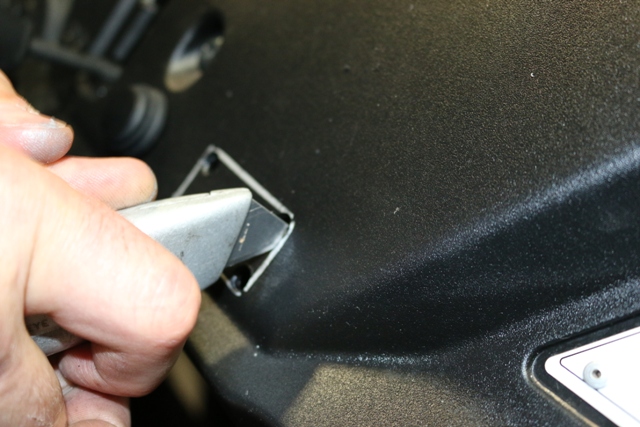
Using a box knife cut out the rectangle.
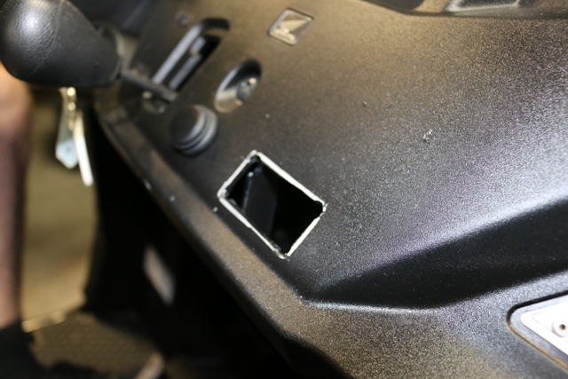
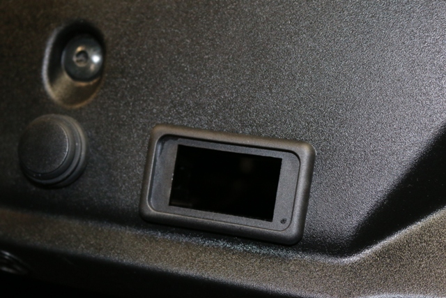
Install Housing
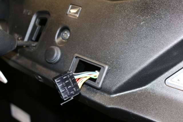
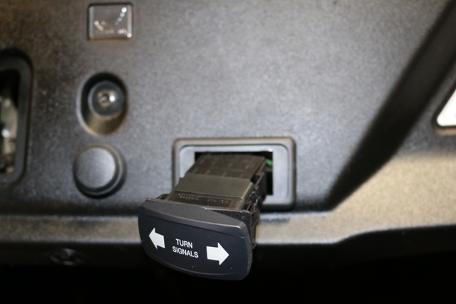
Run Switch wires through opening and attach and slide switch into mount.
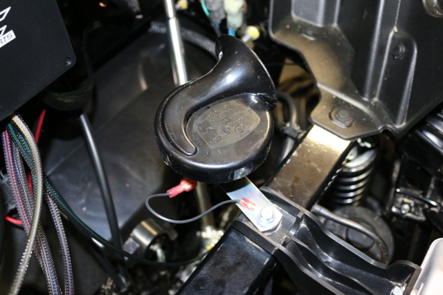
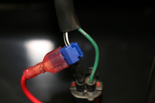
Remove bolt from frame in front and mount the Horn, make sure to attach the horn ground wire as shown. Attach violet wire to other post on Horn.
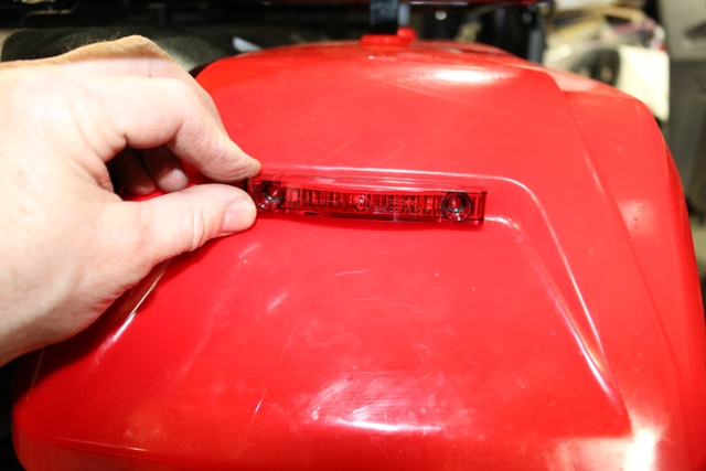
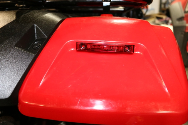
Install 4" LED bar on each rear fender.
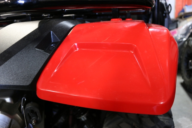
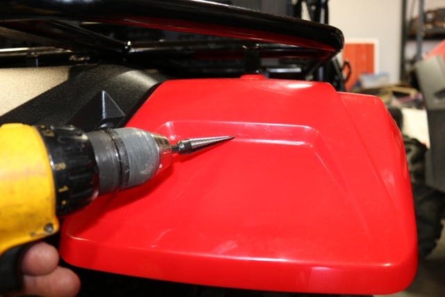
Find center and mark, the light has a oblong tab, drill a small hole and expand to each side to egg it out.
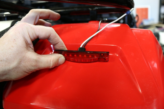
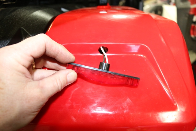
Clean the surface with alcohol and install light with 3M sticky tape provided, optional screws can be installed
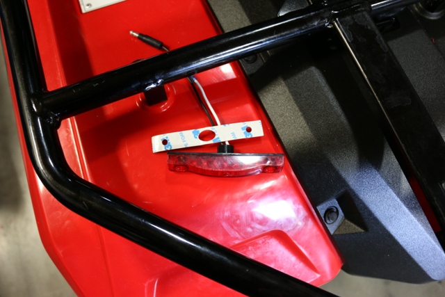
Attach wires to LED and wrap with split loom provided, cable tie harness.
Do the same for the other side.
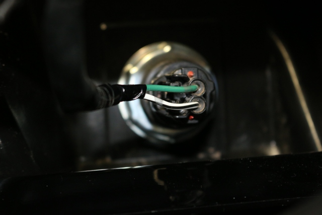
Find the accessory outlet and using the provided tap install on the White wire with Black stripe, install power wire with fuse to this tap.
Optionally the red wire can be attached to another full time power wire so that the Hazard light and Horn work without the key on.
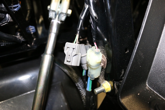
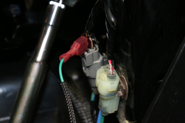
Look for plug near the steering Colum. Attach Green wire using the supplied wire tap. You can unplug from harness to install just make sure you plug it back in.
Verify operation of the system.
The new rear lights operate as brake lights and turn indicators. When the Hazard switch is on rear lights will flash unless the brake is applied and then they will be solid until the brake is released.
Verify that no wires or wire loom is near any hot or moving parts and using the supplied cable ties secure the wires and harness to the vehicle.
We can be reached by email at support@xtcmotorsports.net
or phone during business hours.
Hours are Monday thru Friday 8:30am to 5:30 pm MST and Saturday 9am to 2PM MST
Closed on Sundays
XTC Motorsports LLC
925 N. McQueen Rd.
Suite 101
Gilbert, AZ 85233
480-558-8588
*Disclaimer: This kit is intended for off road use only and XTC Motorsports claims no responsibility for it use. It is up to the purchaser to make sure it complies with all Federal, State and Local laws.
Copyright © 2015 XTC MOTORSPORTS LLC